Frame
Parts List
Hardware
- Nema 17 Motor (x2)
- M3x12mm Bolt w/Round Head (x8)
- M3x25mm Bolt w/Round Head (x2)
- M5x10mm Bolt w/Flat Head (x96)
- M5 T Nut (x96)
- GT2 20 Teeth Pulley 3mm bore (x2 or GT2 No Teeth Pully)
- GT2 No Teeth Pully 3mm bore (x2)
- GT2 20 Teeth Timing Gear 5mm Bore 6mm width (x2)
- 400mm T-Slot Aluminium extrusion (x12)
3D Printed Parts
- Frame Corner Becket (x4)
- Frame Motor Bracket A
- Frame Motor Bracket B
- Frame Idler Pulley Bracket A
- Frame Idler Pulley Bracket B
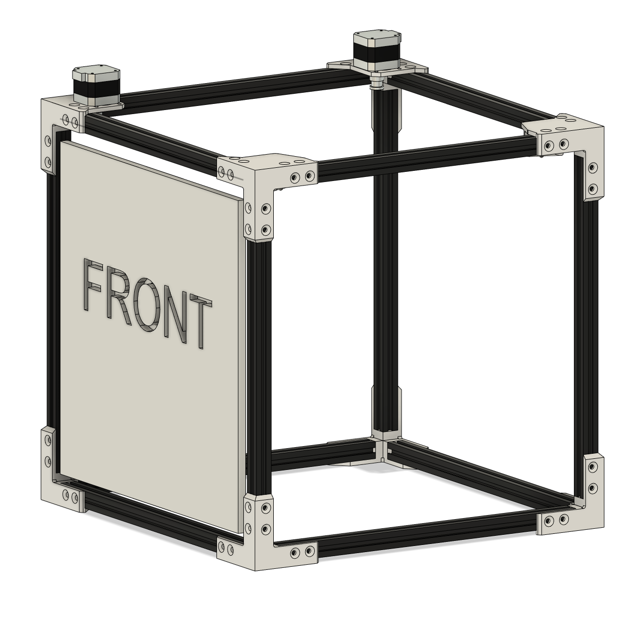
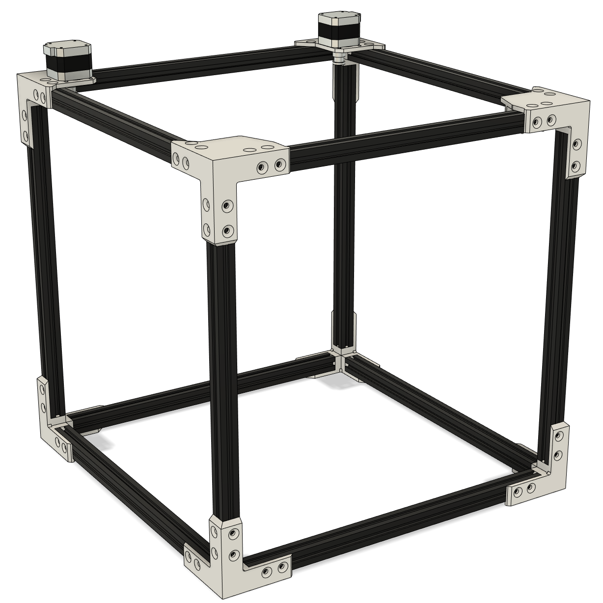
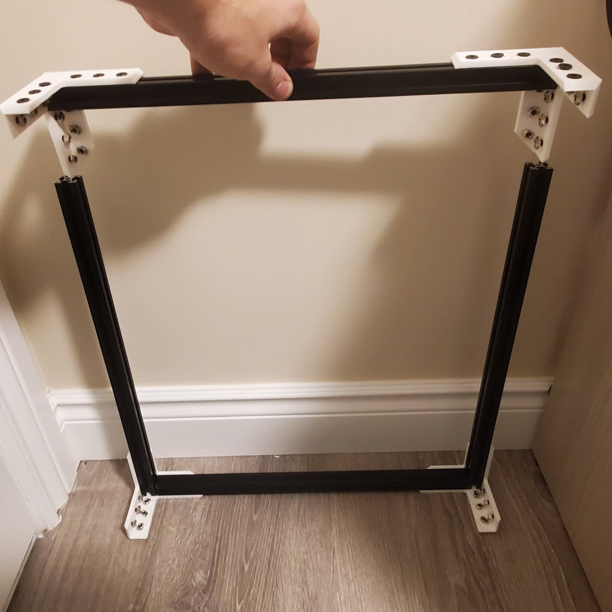
The frame is the main assembly of the printer. Everything attaches to the frame in one way or another. It is important to ensure the frame is square since the performance of the printer will be hampered by a crooked frame. If needed I would recommend measuring the width, length and height and ensuring all the dimensions are the same. If one or dimensions are off you can pull the corner away from the ends of the frame to lengthen a corner. It is not essential for the T-Slot extrusion to butt up against the frame corner, however, it is important everything is straight and equal.
Bottom half
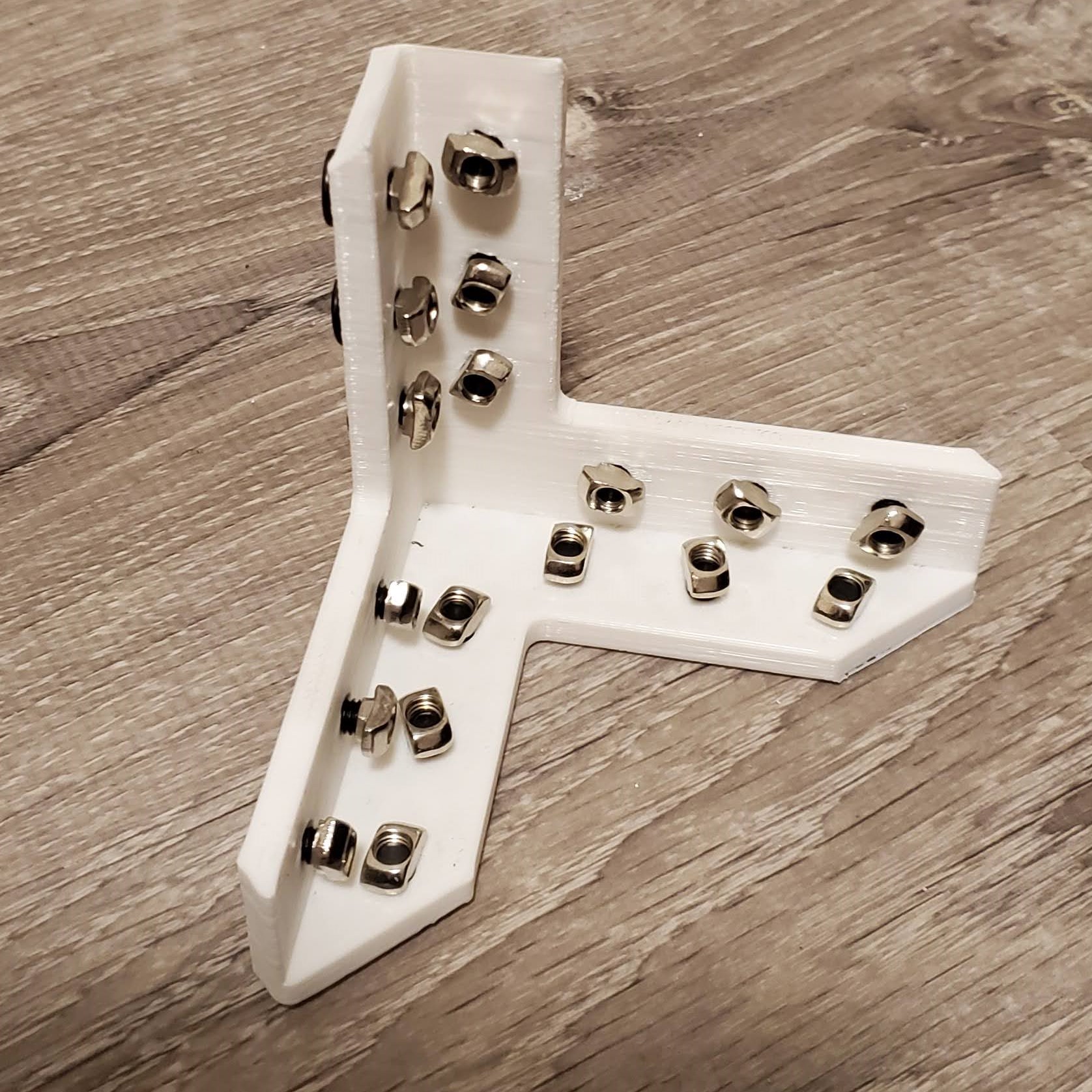
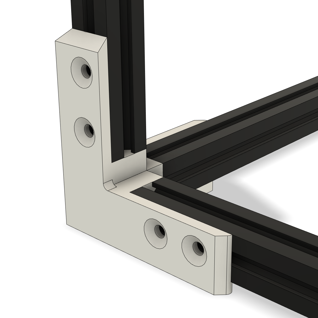
I would recommend starting with the bottom half of the frame. Inset a 5M bolt into each of the holes of the Frame corners and loosely attach a T nut to each bolt. Don’t tighten the nuts yet! Then slide a T-Slot Aluminum extrusion into the frame piece. You may have to adjust the bolts to get them to fit properly. There is a bottom/top to the Frame Corner Brackets, the corner where the edges are not rounded will point up.
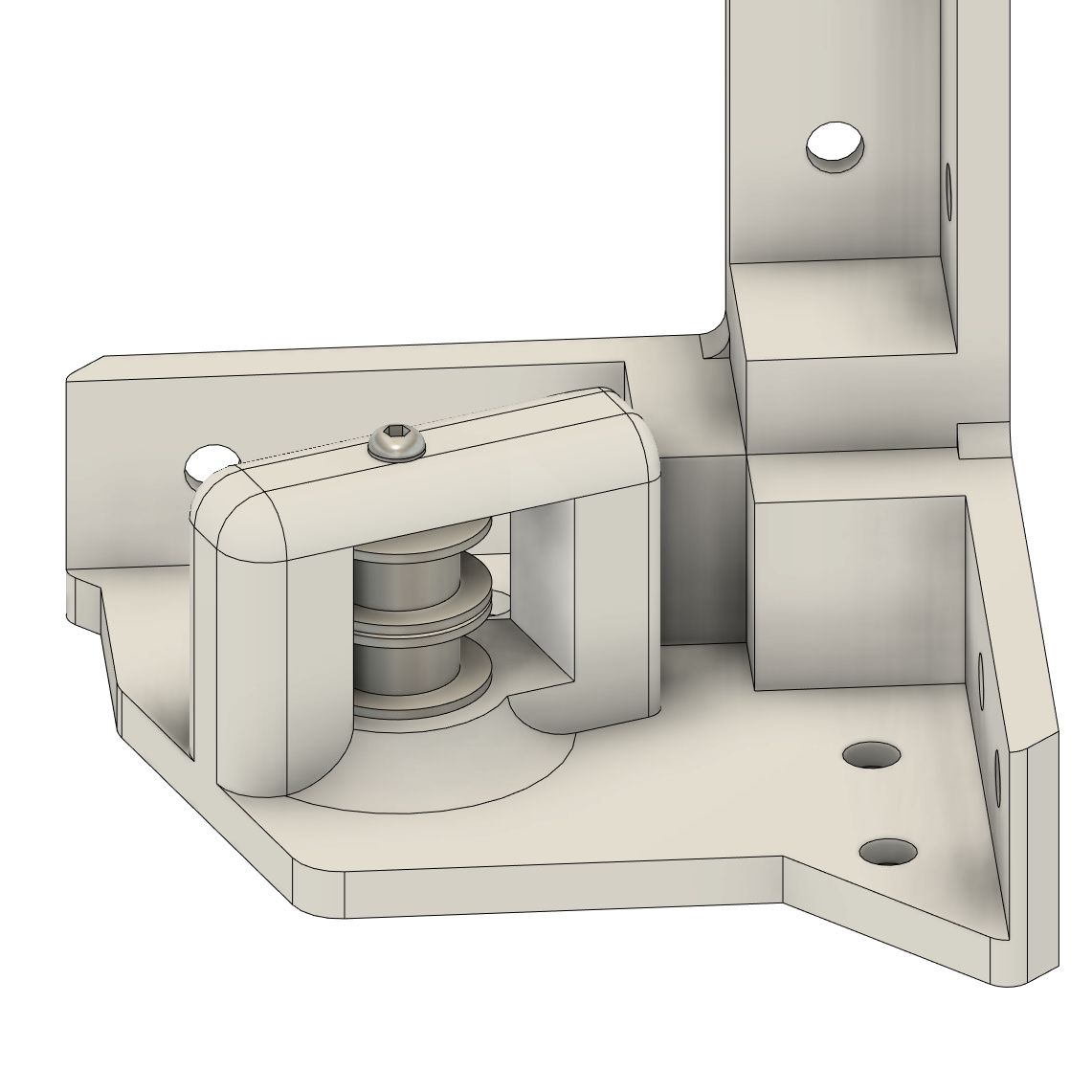
Frame Idler Pulley Bracket
I would recommend installing the Idle pullies into the Frame Idler Pully Bracket before inserting the Aluminum extrusion as it can be hard to insert parts when the frame is assembled. Each Bracket takes 2 GT2 20 Teeth Pulley Gears and an M3x25mm Bolt w/Round Head to hold the gears in place. (If you are using a toothed pully then use 1 toothed pully and 1 non-toothed pully.) The bolt bolts into the plastic. If you are worried about the bolt coming loose during printing you can use a little glue to keep it in place. However, I haven’t had any problems with just a friction fit.
Frame Motor Bracket
I would recommend installing the Nema 17 motors and the GT2 20 Teeth Timing Gear now before inserting the Aluminum extrusion as it can be hard to insert parts when the frame is assembled. Each motor is held on by 4 M3x10mm bolts w/Round Head. Make sure not to tighten up the bots too much yet as we will use these bolts to tighten up the belts once they are installed. Keep the GT2 20 Teeth Timing Gears loose so they can be moved up and down the motor shaft for alignment later.

Top Half
The top of the Frame contains 4 special corner pieces that will hold hardware for the print head transport system (the pullies belts n’ stuff). There are 2 motor mounts and 2 idle pulley mounts. These parts are assembled just like the bottom however, it is very important that the motor and ide pully frame pieces are installed correctly or the belt won’t be able to tensioned or fit correctly. The front of the frame is the motor mounts on the left side and the idle pullies on the right side. When installing the Idle pulley bracket ensure the flat side of the pulley holder faces away from the motors.
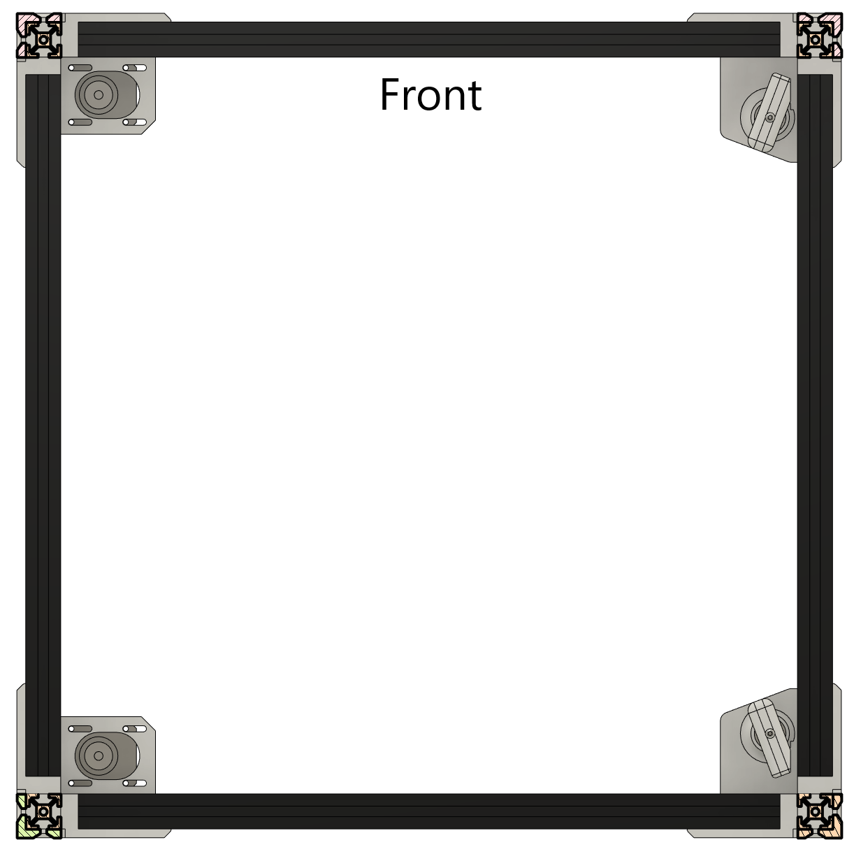
Combine the bottom and top
Finally, combine the bottom and top pieces using 4 400mm T-slot extrusions. From now on I will refer to the front as the side where the two motor brackets are on the left and the idle pulley brackets are on the right. while you can pick a different arraignment as the “front” I would recommend staying to my recommended “front” as it ensures the print head homes in the correct position.