Z-Axis
The Z-Axis is the same between the core and Cartesian designs. It uses 2 stepper motors to hold the print bed level and lead screws to move the bed up and down. The reason OpenBox uses two motors instead of just 1 like other similarly designed printers is for rigidity. Because the parts are printed and because the bed is large and heavy, two attachment points and motors are used. This ensures the print bed does not bind on the linear rales and helps reduce the current draw for each motor, ensuring they don’t overheat (as long as you tune the stepper motor current correctly) as the Z-Axis motors are the only motors that are inside the build chamber (for enclosed builds).
Parts List
Hardware
- Lead Screw 8x350mm (x2)
- Lead Screw 8mm nut (x2)
- Linear Rod 8x450mm (x4)
- LM8UU linear bearing (x4)
- Flexible Coupling 5mm to 8mm (x2)
- NEMA 17 motor (x2)
- M5 Nut (x8)
- M5 T-Nut (x36)
- M5x20 Bolt w/Flat Head (x8)
- M5x10 Bolt w/Flat Head (x36)
- M3 Nuts (x16)
- M3x12 Bolts w/Round Head (x16)
- M2 Nuts (x8)
- M2x12 Bolts (x8) [head type doesn’t matter but round is preferble]
- Lithium Grease for bearings
3D Printed Parts
- Bed Attachment Plate (x2)
- Z-Axis motor holder (x2)
- Z-Axis Bottom Bracket (x2)
- Z-Axis Top Bracket (x2)
- Build Plate Assembly [from part 2]
For easier installation, I suggest doing all the below steps for both parts simultaneously, i.e. both bottom motor brackets, both top brackets, both motor mounts etc.
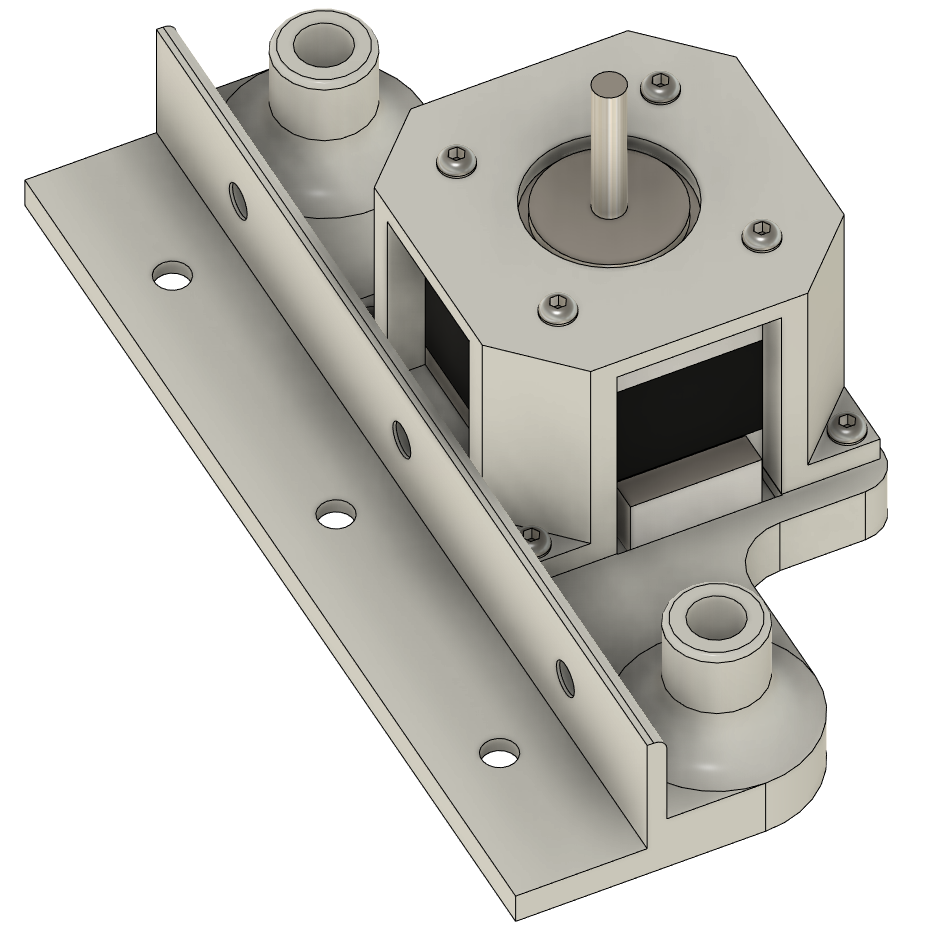
Z-Axis Bottom Bracket
The Bottom Brackets are used to hold the motor and the linear rods in place for the Z-Axis. It is very important that the bracket is securely attached to the Frame.
First, insert the M3 nuts into the bottom of the bracket, this will make motor attachment easier later. Next is the hard part, you will need to install the Bracket onto the frame. I suggest inserting M5x10 Flat Head Bolt‘s into the front of the bracket and attach the T-nuts to the bolts.
Then install the Bottom Brackets onto the left and right side of the frame. It is important for the brackets to be perfectly centred in the frame. A miss-aligned bracket will skew the bed. Once the brackets are aligned tighten the front bolts. Next, you will need to install the T-Nuts and bolts into the bottom of the brackets. Flip the frame over and using something long (I suggest a magnetic screwdriver) push the T-nuts into position, aligning the nut up with one of the mounting holes. then insert a bolt and screw it down. If you find it hard to tighten a bolt back off and try again. It can be easy to cross-thread the bolts as you can’t see what you’re doing.

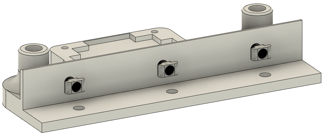
Z-Axis Top Bracket
The top brackets are used to align and hold the Linear rods in position. Installing the top brackets is the same as the bottom just without the M3 nuts. Make sure to install the brackets the correct way up. Installing the brackets backwards won’t affect print quality in any way but it will make installation of the linear rods harder as the brackets have a chamfer to help align the rod into the hole.
Motor Mounts
The Z-Axis Motor mounts hold the NEMA 17 motors to keep them from moving. The motor mounts are one of the few pieces that will need support while printing. I suggest printing the parts face down (with the circular cutout on the build plate) with the 4 tabs being supported with support material. These tabs only keep the motor in place and don’t need to be 100% perfect.
Insert the motor into the bracket (it only fits one way) and bolt it down using 4 M3x12 bolts. Then attach the motors to the bottom bracket using 4 more M3x12 bolts. Make sure to rotate the motor so the connector is facing the way you want it. Finally, attach a flexible coupling to the motor and tighten it down.
If you are using pancake-style NEMA 17 motors to give a little more height in the Z-Axis you will need to modify the motor mounts to fit your motor.
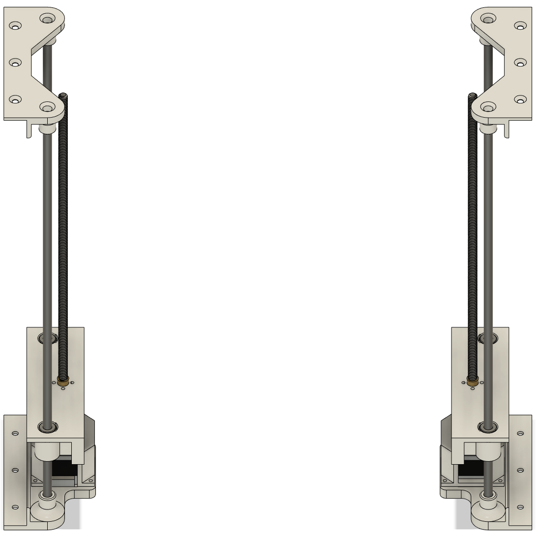
Bed Attachment Plate
The Bed Attachment Plate will ride along the linear rails and is pushed up and down by the lead screw. With the print bed attached to the Bed Attachment Plate, the rotation of the lead screw will translate into vertical movement.
Inset the 2 LM8UU linear bearing and the Lead screw nut into the Bed Attachment Plate. The parts are friction fit and the bearings should be flush with the top of the part. The Lead screw nut should be inserted from below as this will greatly increase the surface area that the nut will have on the part as the bed will push down into the nut instead of into the 4 bolts holding it on. Use 4 M2x12 Bolts and 4 M2 Nuts to securely hold the Lead Screw Nut in place. Finally, insert 4 M5 Nuts into the bolt hols to make bed attachment easier later.

Linear rods and lead screws
NOTE: Before inserting the linear rod into the linear bearing make sure to pack the bearing with grease. skipping this step will lead to excessive wear and makes the bearing loud. Without grease, the bearings can eat into the linear rod in a number of hours. Don’t ask me how I know this!
Installing the linear rods and lead screws is pretty straightforward. I found the easiest way is to insert the linear rods into the top bracket for one side at a time about halfway down, then push the Bed attachment plate up onto the linear rods, using a paper towel to grab any extra grease that will flow out of the bearings, and finally pushing the linear rod all the way down into the bottom bracket. Be careful when pushing the linear rod down! The rods are a friction fit and may bend and even snap the Top bracket if your not careful.

Once the rods are in place use a screwdriver to push the linear rods all the way down, the linear rod will NOT be flush with the top if seated correctly. Insert the lead screws from the top into the Bed attachment plate and into the Spring coupling and tighten the Spring coupling bolt onto the 8mm Lead screw. Rotate the motor so the attachment plate is halfway up the linear rods.
Attach the Build plate assembly.
Make sure both Bed attachment plates are around the same height and push the Build plate assembly in between the two plates and using the M5x20 Bolts, bolt the Build plate assembly into the Bed attachment plates.
If the Build plate assembly is too tight and the linear rods start to bend outwards as you push the bed in then you will need to widen the frame by loosening the frame bolts and pulling the frame apart. The frame doesn’t have to be a perfect square, it can be wider than it is longer, just make sure if you loosen the bottom you also loosen the top. Also as stated in the Frame build instructions, it is ok for the Aluminum extrusions to not be butted up against the corners, everything just needs to be straight and aligned.
If the Build plate assembly doesn’t touch the Bed attachment plates then you can use some washers to fill in the gaps.
