Mainboard and PSU
The Mainboard and PSU are attached to the side of the printer. I won’t be going over wiring so you will have to find other tutorials on how to wire up a printer. If you are using a different mainboard, LCD or power supply you will need to modify these parts to fit what you purchased.
Parts List
Hardware
- BIGTREETECH SKR V1.4 Turbo
- RepRapDiscount Full Graphic Smart Controller
- IEC 320-C14 Plug with fuse and switch
- 360-watt power supply
- M3x10 Bolts w/Round Head (x4)
- M3x10 Bolts w/Flat Head (x4)
- M3x6 Bolts w/Flat Head (x3)
- M3 Nuts (x6)
- M5x10 Bolt w/Flat Head (x3)
- M5 T Nut (x3)
- External Heated bed controller [Recommended but not required]
3D Printed Parts
- Mainboard housing
- Mainboard lid
- Powersupply case
- Powersupply lid
Plug and LCD and PSU
The Plug and LCD you are looking for look like this.

RepRapDiscount Full Graphic Smart Controller

RepRapDiscount Full Graphic Smart Controller – RepRap
Reprap Smart Controller 12864 LCD Display with Smart Controller Board
360-watt power supply

Mainboard
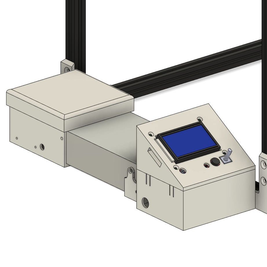
Insert 2 M5x10 Bolts into the right side of the Mainboard housing and attach 2 T nuts to the M5 bolts. The Mainboard is heald in with 2 M3x8 Bolts at the top of the mainboard. You will probably want to keep the main board loose so you can easily remove it when wiring it up.

The LCD is healed on with 4 M3x8 Bolts and 4 M3 Nuts. Mount the Mainboard case to the left side of the printer and push it as far forward as possible. It should touch the front bracket. Once in place tighten down the M5 bolts.
Power Supply
Insert the IEC 320-C14 Plug into the Power Supply Case and bolt it in place with 2 M3x10 bolts w/Round Heads and 2 M3 Nuts, (you may want to attach the wires first before inserting the IEC 320-C14 Plug). Insert an M5x10 Bolt into the Power Supply Case and attach a T Nut. Bolt the Power Supply Case to the left side of the printer and push it all the way back until it hits the corner bracket. Unlike before don’t tighten the M5 Bolt just yet.

Place the Power Supply in between the Power Supply Case and the Mainboard case. Now push the Power Supply against the Mainboard case and attach the M3x6 bolts. (note not all power supplies will be able to be attached with all 3 bolts, I only have 2 bolts holding mine in) Next push the Power Supply Case into position so the holes line up with the Power supply, attach the remaining M3x6 bolts. Finally, Tighten the Power Supply Case M5 Bolts and attach the Lids to the two cases.