X-Axis and Y-Axis
Parts List
Hardware
- Linear rods 8x400mm (x4)
- GT2 3mm bore 20 teeth timing pully (x2) [or no teeth version]
- GT2 3mm bore timing pully (x2)
- LM8UU Linear bearing (x4)
- M5x10mm Bolt w/Flat Head (x16)
- M5 T Nut (x16)
- M3x30mm Bolt w/Flat head (x2)
- Lithium Grease for bearings
3D Printed Parts
- Linear rod bracket A (x2)
- Linear rod bracket B (x2)
- X-Axis Linear Rod Mount (x2)
- Extruder Mount Plate
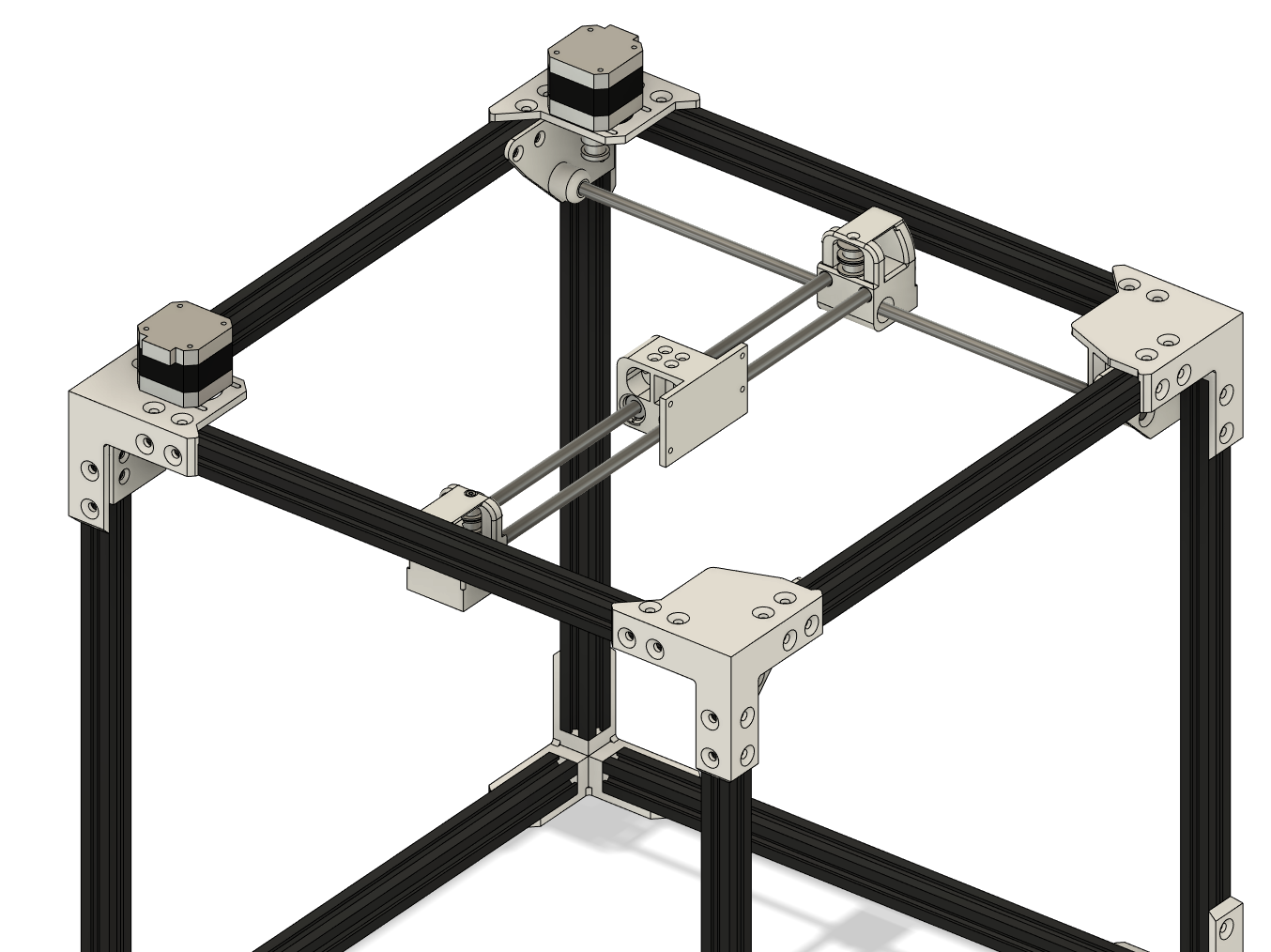
Linear Rod Brackets
The X-axis and Y-axis are held on by the 4 Linear rod brackets. Insert the 4 M5 bolts and T Nuts into the bracket and put them in the corners of the frame. Note there are two types of brackets. You know you have the correct corner bracket installed in the correct corner as the cylindrical protrusion will be on the inside of the frame.
Linear Bearings
Insert the Linear bearings into the 2 X-Axis Linear Rod Mounts and the Extruder Mount Plate. The Linear bearings are a friction fit so if yours are too lose you may need to add some glue to hold them in place or if they are too tight you may need to sand down the inside of the hole. Try to get the bearings as close to the center as possible. You may want to use another bearing to help you push the bearing into place. Next, make sure you pack your linear bearings with some lithium grease. Forgetting this step will wear out the bearings or rods prematurely.
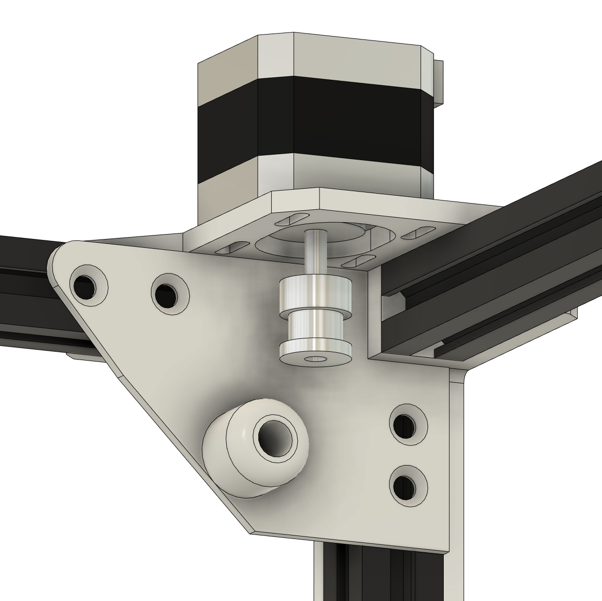
X-Axis
First, place 1 toothed GT2 pully and 1 non-toothed GT2 pully (or just 2 non-toothed pullies if you are not using toothed pullies) into the X-Axis Linear Rod Mount and insert the M3x30 bolt into the top to hold the pulleys in place. Don’t tighten the bolt too tight as you don’t want to strip the plastic (you can heat tap a threaded insert into the part if you wish but this is not necessary). Repeat this for the other X-Axis Linear Rod Mount but make sure to switch the pulleys. So if the toothed pully was on the tap put it on the bottom for the second Mount.

These next steps may get a little confusing, if you find yourself confused then just make sure that the flat part of the Extruder Mount plate is facing the right side of the printer.
If you are using the Wham Bam Extruder Plate make sure to install the threaded inserts first!
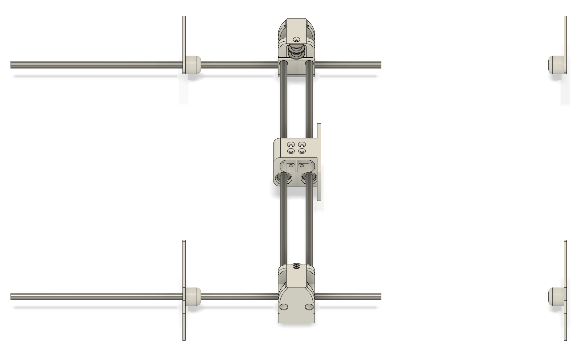
Insert 2 linear rods into the X-Axis Linear Rod Mount that has the Toothed pully on the top. Only insert the linear rods about halfway through the part. Note the back of this part is the side opposite the pulleys. (the image above shows the part in the correct orientation with the front facing you.) With the X-Axis Linear Rod Mount close to you and the two ends of the rod farthest away from you slide the Extruder Mount plate onto the linear rods with the flat part of the plate pointing right.
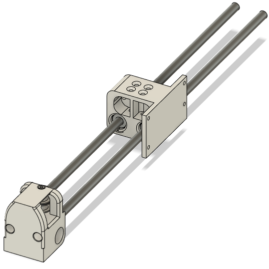
Next insert the X-Axis Linear Rod Mount to the other side of the linear rods.
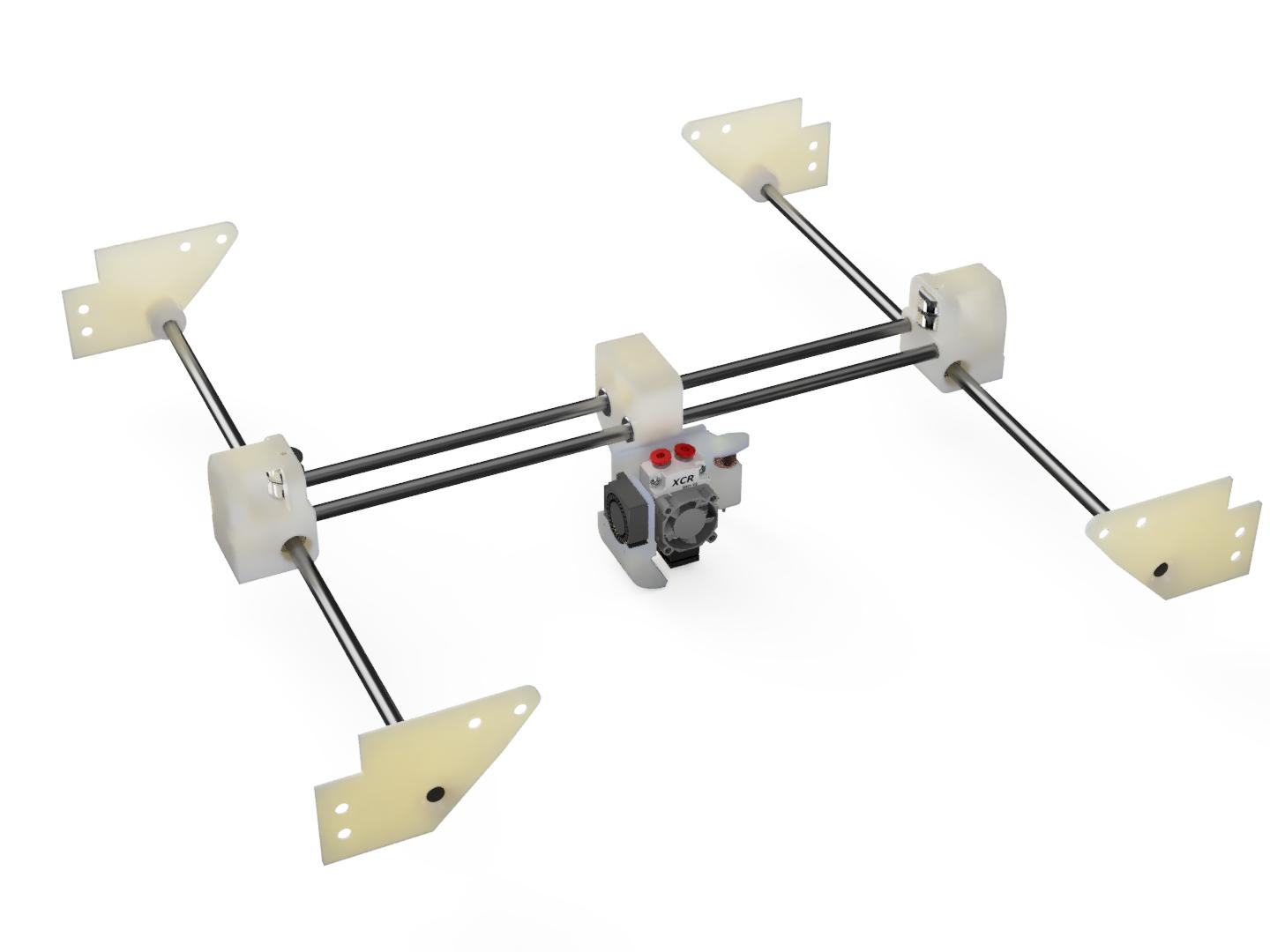
Y-Axis
Insert the last 2 linear rods halfway through the left brackets, then slide the X-axis onto the two half inserted Y-Axis Linear rods, (you may have to adjust the X-Axis so it fits on the Y-Axis).
Push the linear rods through to the other Linear rod brackets.
The X-Axis and Y-Axis should move freely. if not adjust the distance between the 2 X-Axis Linear Rod Mounts. You may find the Y-Axis binds on itself if it becomes two skewed. This is ok, when the belt is attached it will keep the pars from skewing too far and binding on the bearings.